


Audi A4 / B8 ACC Adaptive Cruise Control / Active radar / Basic Instrument Cluster conversion to full ACC unit / IC conversion
Hi Folks,
After successful ACC retrofit and garage made ??calibration on my A4 / B8 / 2011 / 1.8 TFSI, I have Decided to take up the project of basic instrument cluster conversion to full ACC one ... inspired by HanneSQ5 and Karlonimo work on IC ACC convention 
Project what of basically driven by the factthat I received a secondhand ACC instrument cluster 8K0920930 G (declared as faulty- reporting fault 16348 - Control Module - Checksum Error, 014 - Defective) and Decided to use it as LEDs, NEC D6345 microcontroller, diode , transistor, capacitor donor as well as donor of black gauge dash faceplate scaled in km housing 23 LEDs All which is different than the one on non ACC IC.
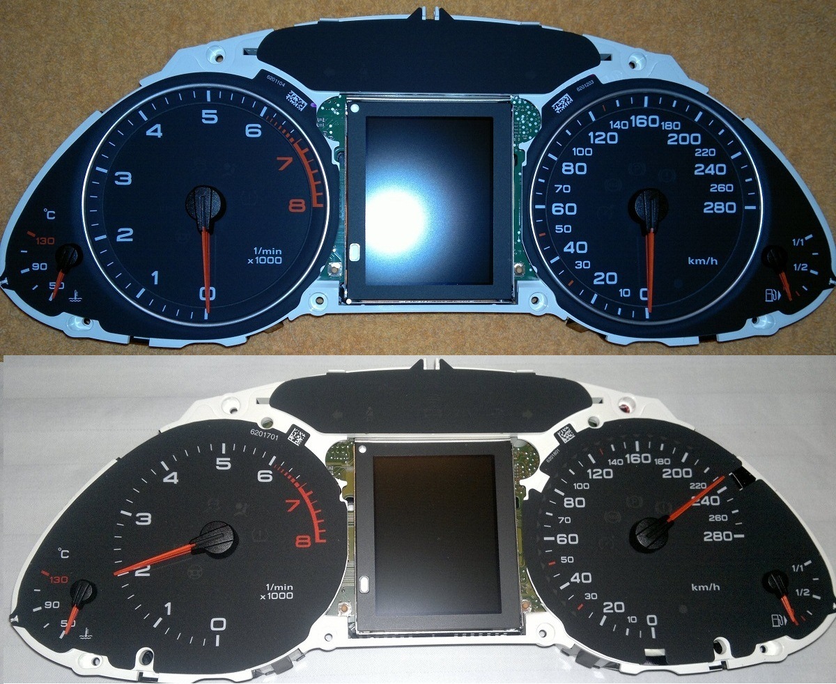
black gauges dash faceplate difference
Benefit - Upgrading all LEDs on my original instrument cluster part no: 8K0920930 M (benzine) to version "G", "T" or "Q" Allows to keep original mileage status, efficiency program and Eliminates necessity of CP removal from retrofitted ACC IC ,

ACC IC as per ETKA
I have care fully study PCB boards of Both ACC and ACC non IC and marked all missing components on non ACC IC "M".
As a first easyStep I have successfully re-solder 6 LEDs (3 red +3 green) + 6 Resistors (3 x 331ohm and 3 x 301ohm) on my original IC, (LED on top middle part of IC showing ACC status) tested and confirmed all worked well J.

ACC LEDs

SMD LEDs

Resistors to be re-solder

Missing resistors
Spare ACC IC is required as front black gauge dash faceplate is different and need to be moved to your original IC (non ACC)


Then of studied again Both boards and Decided to go and re-solder 23 LEDs around speedometer, resistors and other components missing Allowing speedometer LEDs to work.
There are 3 x NEC D6345 microcontrollers (each is a driver for 8 LEDs total of 24 LED can be served) - ACC use 23 LEDs the load NEC controller uses only 7 outputs (for more info refer to NEC D6345 Datasheet.pdf).
NEC -1 lights up LEDs from speed 30-65kmh - LED 1-8 (5km step)
NEC -2 lights up LEDs from speed 70-130kmh - LED 9-16 (5 / 10km step)
NEC -3 lights up LEDs from speed 150-200kmh - LED 17-23 (10km step)


Missing 23 red SMD LEDs

Missing 23 LEDs 271 ohm resistors (LED resistor number)


All marked 23 SMD LEDs need to be re-solder


All marked components need to be re-solder ( NEC D6345 microcontrollers, diodes, transistors, capacitor s r)


All marked components need to be re-solder ( NEC D6345 microcontrollers, diodes, transistors, capacitor s)

Orginal IC ACC PCB
Once finished I tested my "converted" IC and surprisingly all started to work well. I got fully function ACC instrument cluster. HOWEVER, I it turned out that last 5 LEDs responsible for 160, 170, 180, 190, 200km speed do not light up L. All the rest worked well. VCDS Output test of Unit-16 confirmed that last 5 LEDs got some physical trouble. I have Individually tested load 5 LED separately (3V + resistor connected to each) and confirmed that last 5 LEDs were not broken.
Again went back to do some research and troubleshooting on PCB.
I found out, dass die same NEC - 3 microcontroller Correctly lights up LED 17 / 140km and LED 18 / 150km.
So in total only 18 x LEDs around speedometer were operational, LEDs 19-23 (160-200kmh) did not work for that moment.
After deeper analysis of PCB I found out that:
- LEDs 1-18 (30-150km) - forms group of LEDs "+" anode connected directly to Positive.
- LED 19 (160km) - LED "+" anode is connected via Individually small PNP transistor (XUs) to Positive.
- LEDs 20-23 (170-200km) - forms next group of LEDs with bridge LED "+" anode to Positive via the same PNP transistor (XUs)
It is correct as NEC controllers Provide Negative connection to ground in order to light up every single LED. So there is common Positive connected to all 23 LEDs, except some additional control function for last 5 LEDs. Unfortunately I was not able to track Further connection of basically as copper circuits lines got lost somewhere between 4 layers of PCB.

23 LED diagram

4 layer PCB
Again I of studied the circuit board layout and figured out did two of re-soldered components Could become faulty or overheated. But on the sametime I did Realized I could try to make it simpler and Provide Positive common connection through the rest of LEDs. As on IC PCB there what already place designed for a small component (guess resistor 0 ohm) I Decided to bridge it (A) (providing common POSITIVE to all 23 LEDs: as shown in the diagram) and test.

No need two marked components, bridge or 0 ohm resistor is required

2 x marked 0 ohm resistors (= bridge) need to re-soldered to an extra bridge need be added

No need two marked components
BINGO!!! - After IC cluster test all 23 LEDs light up!
VCDS 16 - Output HW testing and real test drive confirmed did all 23 LED can be Individually switched ON / OFF.
Conclusion:
Non ACC instrument cluster (with on board integrated Fujitsu chip MB91F366GC) has got full SW futures supporting ACC functions on.
Four Layers PCB used on Audi A4 / B8, ACC and ACC non IC are Exactly the same PCB but the only difference is of specially installed components supporting functions on ACC.
I need to make it clear to everyone did it is VERY PRECISION WORK and requires advanced soldering skills. Some of the components are extremely small and general knowledge of electronic component is mandatory here. IC PCB is 4 layer PCB and when applying hot air gun work attention is required to avoid component overheating and PCB damage.
Re-soldering process requires special tools (soldering station, Including hot air gun, soldering paste and magnificent glass)
Quite risky project but on the end you receive an award of fully functional ACC IC 
Great respect goes to: HanneSQ5, Karlonimo
EDIT ... UPDATE: 2016-04-01
I was contacted by user who did find out that there is one more missing component - resistor - near CPU. This component seems to be responsible for providing current to light up last 5 LED.

Extra resistor near CPU
As you can read my blog above I did find a workaround solution providing a "bridging" so 5 LEDs will work.
So if anyone attempts to go ahead with IC retrofit - please resolder all selected components including resistor near CPU as on the picture. Test IC and report if all works well.
If last 5 LEDs are not working go ahead and apply my workaround solution.
Thanks to here goes: Jarle 
Kommentare 5
Obelix72
Spiele auch schon seit einiger Zeit das bei meinem KI zu machen ... Habe jetzt mal die NEC, LED's und Wiederstände bestellt. Sobald alles da ist werde ich das Projekt starten. Mal schauen ob's funktioniert.
MartinA48K
That´s awesome.. This detailed Information because A4 B8 ACC is the best, that i´ve ever seen on web. Could anyone translate that infos into german language please? ..Thanks
QueenMaja
Just amazing!
Lisi
i have converted all LEDs of a VW Golf V GTI Instrument Cluster from blue to white and i know, that it is a lot of work and you have to be very carefully. But i am surprised that it is so "easy" to convert the IC and get a functional ACC version. Very good work :-)
WINMAN
Thank you very much for this great Blog entry!!!! It's really one of the best.